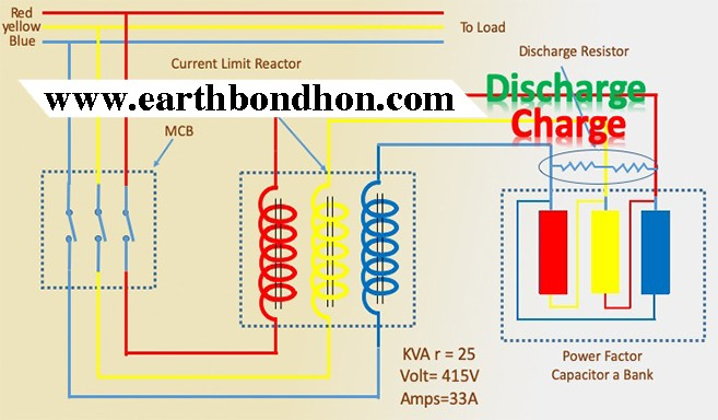
Capacitor Bank Wiring Diagram
Reactive power compensation panel factor correction capacitors kvar capacitor bank working symbol connection the circuit diagram of single phase circuitry for improvement wiring modes alpes which type 11 kv tepco what is a electrical using with 3 line. Wiring of power factor relay on lv and mv side circuit diagrams eep.
☑ Connection 3 Phase Capacitor Bank Wiring Diagram
Rvt modbus for a maximum protection of your capacitor bank against temporary deterioration of your network quality.
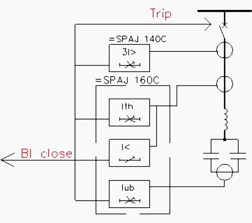
Capacitor bank wiring diagram. Capacitors may retain a charge long after power is removed from a circuit; Capacitor bank capacitor bank types. An introduction to capacitor based power factor correction circuits passive components blog.
Electric motor starting capacitor wiring installation. This helps in improving the power factor. It shows the elements of the circuit as simplified shapes, and the power as well as signal links between the gadgets.
If you see a “sw” instead of a number, you are looking at a switched shunt compensator (see above). A wiring diagram is a simplified standard pictorial depiction of an electric circuit. If switches are provided with the capacitor bank, the switch contacts must remain closed during transportation and handling.
• rvt controller (for apcm1, apcm2 and apcr only). It includes directions and diagrams for various varieties of wiring techniques and other products like lights, home windows, etc. The circuit diagram of the 555 timer in astable mode is shown below.
Step by tutorial for building capacitor bank and reactive power compensation panel eep. Each component should be placed and connected with other parts in particular manner. Capacitor leakage tester circuit find.
The diagrams below show capacitor connections for typical starting circuits for reduced voltage motor controllers. An unbalance protection device (current relay and transformer) continuously monitors the unbalance current between two neutral points and, in the event of faults in a capacitor, opens the bank control. Test and operate all switches and secondary accessory equipment.
Generally, the unit of a capacitor bank is known as a capacitor unit. Capacitor bank shall continue to operate upon isolation and loss of a single stage to match reactive power requirements of system as closely as possible. Make sure that the circuit matches the actual motor diagram before applying capacitors.
Each component ought to be placed and linked to different parts in. The recommended wire size is. Complete wiring diagrams showing connections of component devices and equipment.
Connection diagrams for factor correction capacitors kvar guide the circuit diagram of single phase power system. The capacitors should only be on line when the load requires kvar and disconnected when the load is reduced. In the delta, the line voltage is equal to the phase voltage.
3 phase capacitor bank wiring diagram sample may 11, 2018 by headcontrolsystem collection of 3 phase capacitor bank wiring diagram. Check for proper wiring of the capacitor units. It shows the components of the circuit as simplified shapes, and
Refer to figure 2 8. Conductor size can be determined from a wire size chart. Capacitor bank capacitor banks are represented as a capacitor at the end of a line.
The best marginal is always to use a verified and accurate power factor correction capacitor wiring diagram that’s provided from a trusted source. If not, the structure will not. This charge can cause dangerous or even potentially fatal shocks or damage connected equipment.
Capacitor bank control wiring diagram. Read mitsubishi mini split wiring diagram. 2 circuit diagram of power factor improvement and controller scientific.
The wire size from the auxiliary capacitor bank to the 3 ph motor may be determined by the following formula which will calculate the amperage rating of the circuit. Squirrel cage capacitor wiring diagram. Three phase capacitor bank wiring diagram as shown in the above figure, 2 capacitor banks have been connected to the grid.
Circuit diagram of single phase capacitor run induction furnace fan squirrel cage er motor bank connection on start motors machine wiring electrical power conversion systems do we use capacitors in angle grinder how to wire a acp m ac. Putting all these diagrams together, one obtains complete control circuit diagram for the capacitor bank. The schematic diagram for a permanent split capacitor motor is shown in fig.
All these are connected in delta. Circuit diagram of single phase capacitor start induction motor with. The number on top (or on the left if the capacitor is shown vertical) indicates the real charge admittance, gshunt, of the line (0.0mw).
• top cable entry (for apcm1, apcm2 and apcr only).
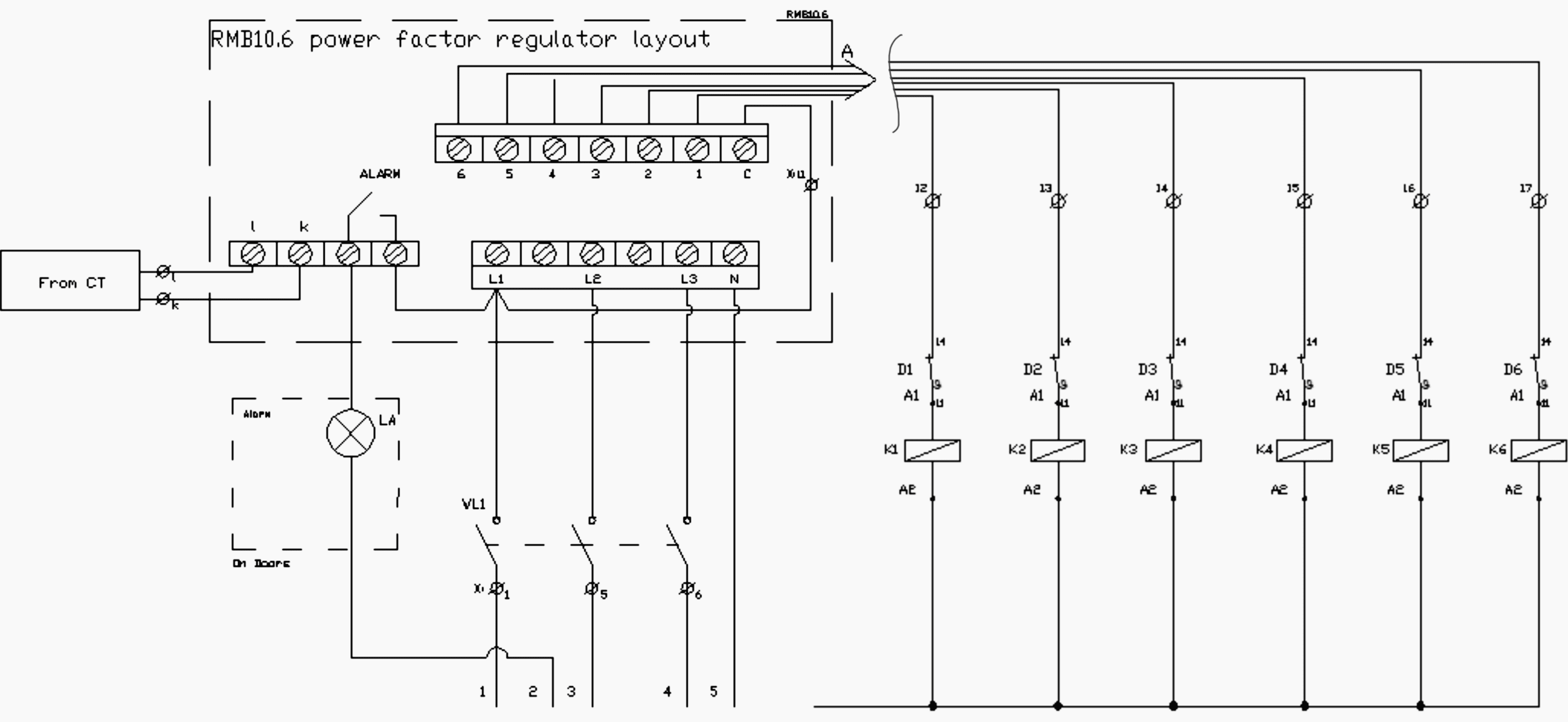
Stepbystep tutorial for building capacitor bank and reactive power compensation panel EEP

Basic circuit of a capacitor bank; L, C, R and R C represent the wiring... Download Scientific

3 Phase Capacitor Bank Wiring Diagram Free Wiring Diagram

Capacitor Bank Control Wiring Diagram

Schematic diagram of the capacitor bank pulsed power system. Download Scientific Diagram

The basics of capacitor banks protection EEP
Discharge behavior of capacitor banks

How To Connect Capacitor Bank To Improve Power Factor Bank Western
Wiring Diagram Capacitor Bank yazminahmed

Protection of double star capacitor banks Capacitors, Power, Protection
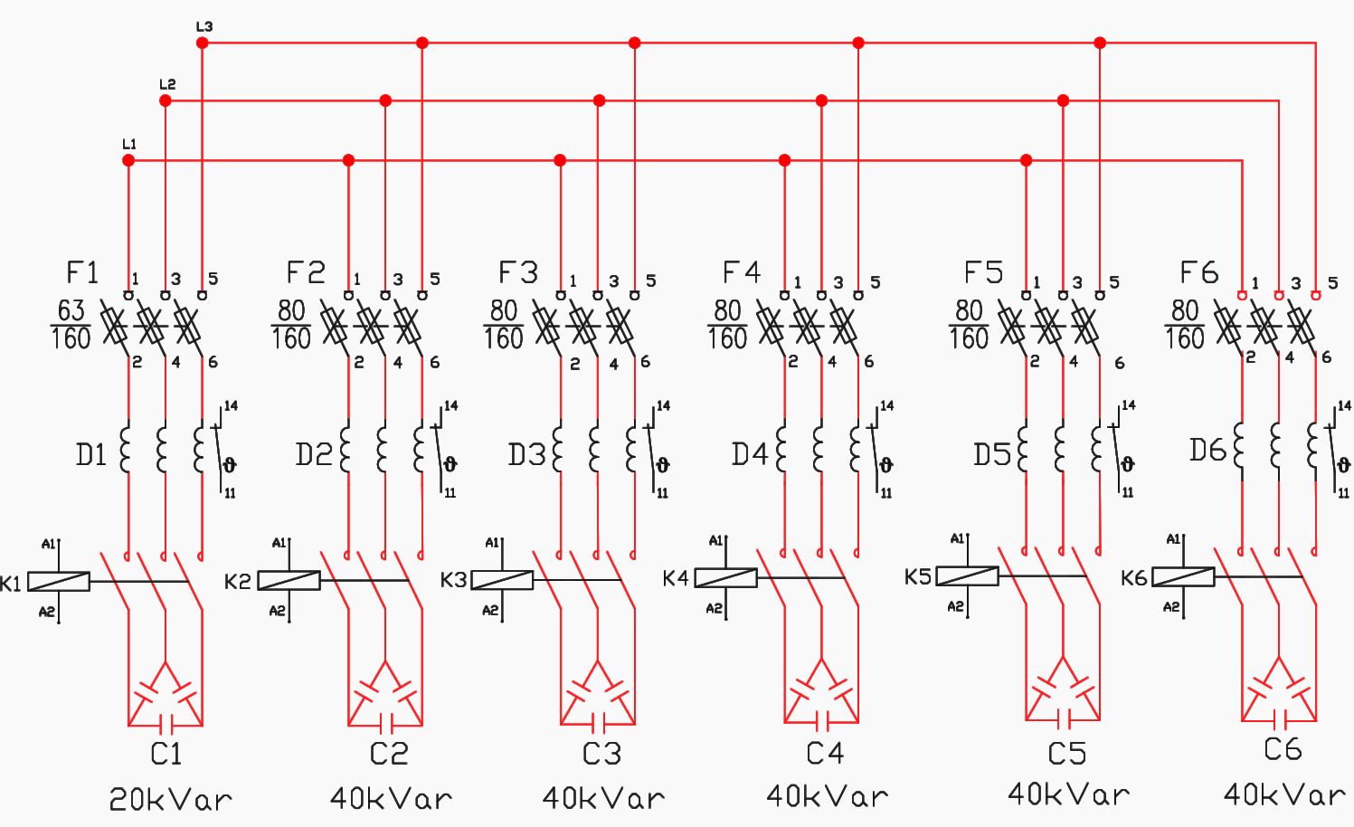
Stepbystep tutorial for building capacitor bank and reactive power compensation panel EEP
Power Factor 3 Phase Capacitor Bank Wiring Diagram Electronic Diagram
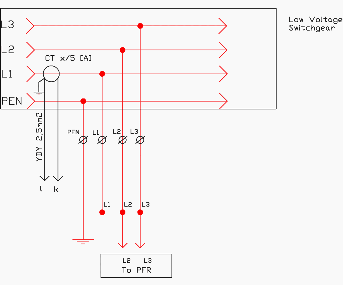
Stepbystep tutorial for building capacitor bank and reactive power compensation panel EEP

Switchable Capacitor Bank or Switched Capacitor Bank Electrical4U
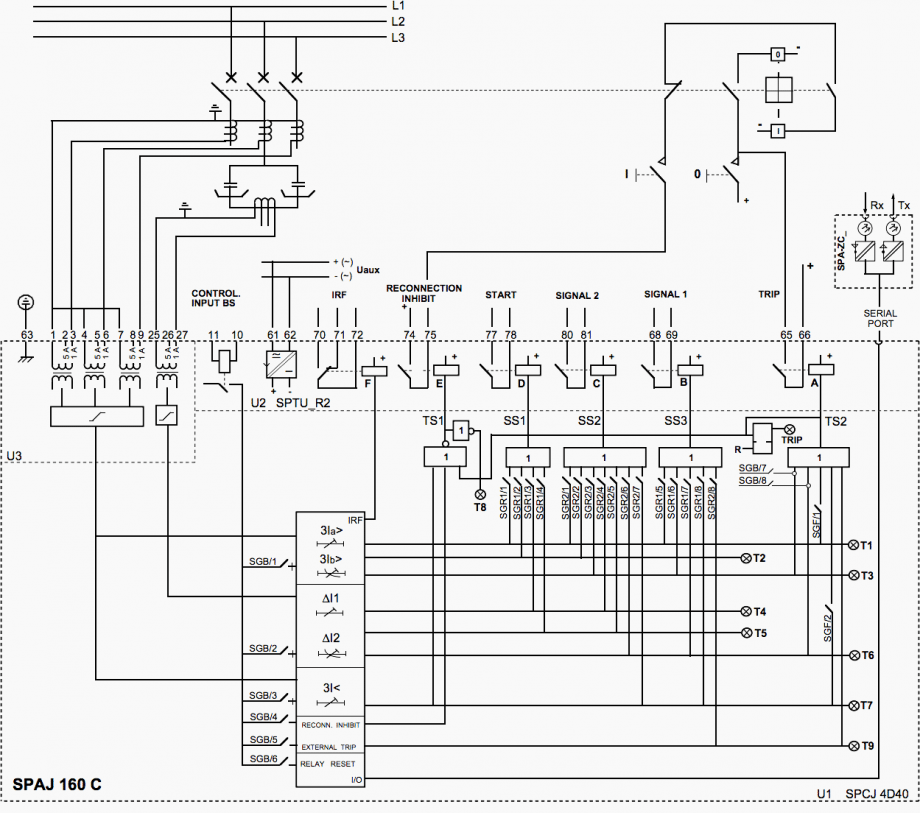
The basics of capacitor banks protection EEP
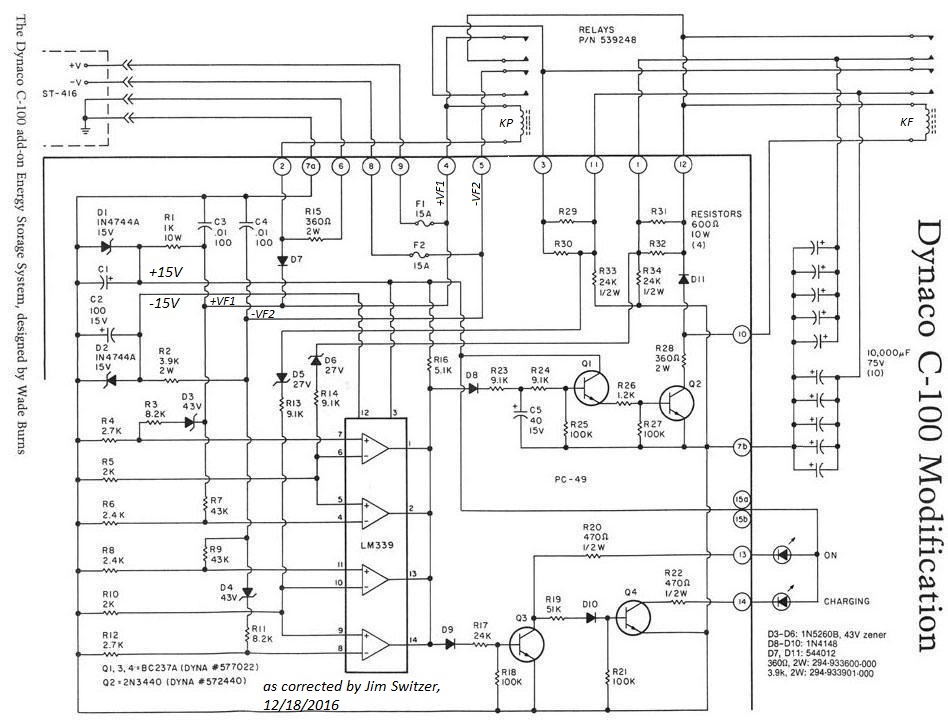
3 Phase Capacitor Bank Wiring Diagram Seputar Bank

3 Phase Capacitor Bank Wiring Diagram
Connection 3 Phase Capacitor Bank Wiring Diagram Electronic Diagram


